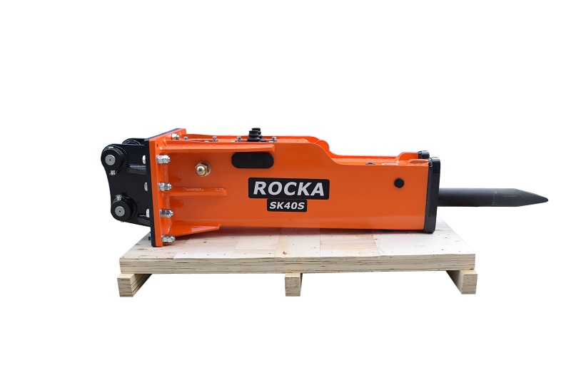
How to mount the hydraulic breaker?
Mounting the Breaker
Clean the inner surfaces of the breaker attachment bracket with a cloth.
Draw the carrier machine near inserting the STICK boom into the breaker attachment bracket.
Carefully clean any dirt from the pins and bushing. Insert the bucket pin checking its alignment and securing it with the collars and locking bolts.
Move the LINK cylinder to line up the hole of the connecting rod with the second mounting bracket attachment hole. Insert the pin and secure it with the collars and locking bolts.
▲CAUTION!
Do not force the pin; re-check its alignment instead.
1 Setting The Pressure
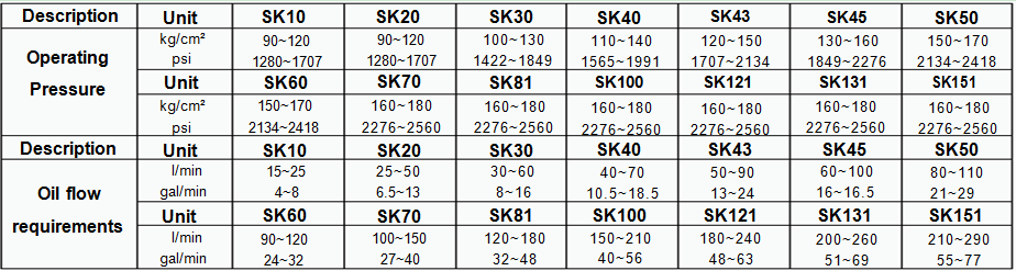
See “Specifications” below for operating pressure and oil flow requirements for all Rocka models.
▲CAUTION!
DO NOT operate the breaker below its minimum flow rate. Internal damage to the breaker may result.
DO NOT operate the breaker at a pressure near to or above the relief valve setting. Internal damage to the relief valve may result. Ensure the relief valve is set 400-600 psi (27-41 bar) above the actual operating pressure of the breaker.
2 Setting the Flow
Install an in-line flow meter in place of the breaker.
Adjust the flow on the flow control valve to the maximum permitted for the breaker. The highest flow will permit the most blows per minute.
Ensure the flow is within the permitted range.
3 Setting the Relief pressure
Connect a flow and pressure meter in place of the breaker. (Bypass the hydraulic breaker and route the return line directly to the tank.)
Measure the flow under no load and verify it is in the range for the breaker.
Slowly increase the pressure and at the same time, verify the flow remains constant right up to the predetermined relief setting.
Adjust accordingly. Double check both relief pressure and flow settings.
When the breaker is installed and the oil is warmed to operating temperature, use a pressure gauge in the pressure line to verify the average operating pressure is within the specification.
4 Start-up
Before putting the breaker to work in hard material, it is necessary to remove air from the hydraulic system and allow the new seals to work in properly.
Lift the unit off the ground.
Press the start button or pedal to fire the breaker momentarily.
Continue to turn the breaker ON and OFF in this manner for 10 minutes.
Work the breaker in soft material in short bursts for 10 minutes.
Check for any loose bolts or oil leakage. The breaker is now ready to operate.
On new units, be sure the Installation Notice is properly completed and submitted.
5 Typical hydraulic Circuits
For a hydraulic breaker to function, it needs hydraulic flow and pressure in one direction only. The supply line should be directed out the left side of the carrier and the return line on the right (as viewed by the operator).
ROCKA breakers operate within a specified flow range. The operating pressure will depend on the amount of oil flow, the return line pressure, and internal efficiency of the individual attachment.
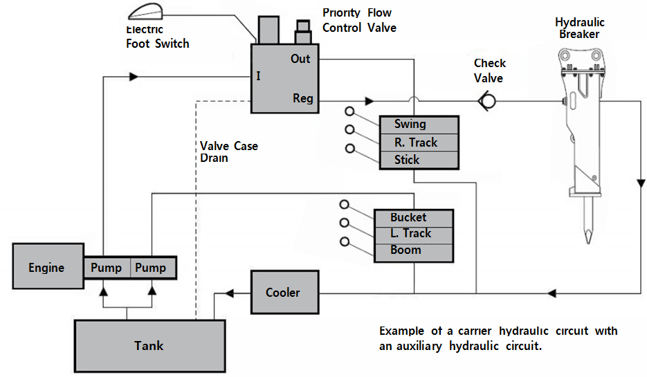
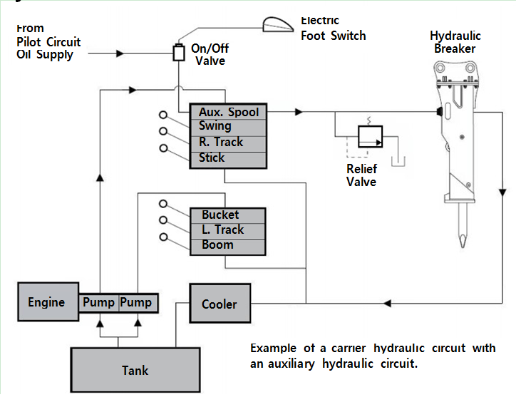
6 Carrier with Auxiliary Hydraulic Circuit
The carrier will often be equipped with an auxiliary control valve. In this case the auxiliary control can be used to control the supply of oil. It can usually be adjusted to provide the correct amount of flow, and a relief cartridge can be installed to protect the hydraulic circuit.
▲CAUTION!
When using the carrier’s existing auxiliary control valve for the hydraulic breaker circuit, do not route the return line back through its return port. High back-pressures may result.
It is recommended to send the oil directly back through the cooler/return filter to the tank.
If it is necessary to plumb the circuit using both ports on the auxiliary valve, the return line should have a drain line connected to the tank. This will reduce back-pressure in the hydraulic circuit and protect the control valve from return line pressure spikes.
 Typical hydraulic Circuits
7 Carrier without Auxiliary Hydraulic Circuit
If the carrier is not equipped with an auxiliary control valve, install a priority flow control valve to direct the correct flow away from the normal circuit and operate the attachment.
The priority flow control valve is usually equipped with a flow adjustment and pressure relief. These valves often need a check valve on the regulated port to completely close the flow. If dividing too much flow, this circuit can generate heat and may require additional cooling capacity.